
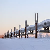
 Advanced modelling and simulation in pipelines cover a wide domain in process engineering, fluid transportation, mechanics of process equipment and safety devices. Innovative simulators built on most state-of-the-art technology help designing a completely new pipeline network that runs at optimal efficiency or expanding an existing one.
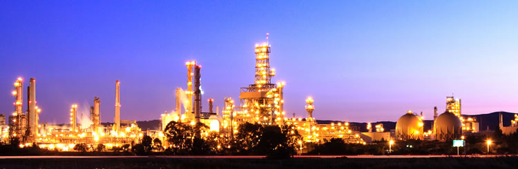
Innovative Simulations
 Plant safety requires items of plant and equipment accomplish safety-critical features which need to be realized by accurate design procedures and installation and during maintenance carried out as part of a planned programme or emergency work. Quantitative analysis of the rapid depressurisation of vessels or pipelines is an essential task during the design and safety analysis of Oil & Gas facilities and other high-pressure installations.
Plant Safety
 The simulator takes an active participation in the pipeline operations in ensuring safety and economy. Steady-state simulations provide flow assurance workflows for front-end system design, line modifications and production operations. Transient state implies the effect of time over the operational behaviour of an industrial facility. Successful pipeline operations is achieving the profit optimality by the correct management of the capacity, inventory, and storage while avoiding losses and minimizing the operational cost.
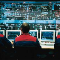
Role of Simulator in Pipeline Operations
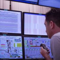 A necessary component of plant’s safety management is the training of operating personnel. Participating operating personnel could experience the behaviour of pipeline under widely different operating conditions, the practical significance of operating limits and the manipulation of operating parameters for the optimal results. ‘What if’ querying, investigating safe operating limits, process optimization, planning and scheduling can be experienced from offline simulation.
Operator Training
 Fluid thermophysical properties are specific to the operation and in most industrial applications the thermophysical software is developed and validated separately in accordance with the client specifications before the properties are incorporated with the simulation software. GB Simulation Technology simulation software can also be integrated with most externally available thermophysical property packages. Some of the GB Simulation Technology thermophysical property software has been released as standalone programs.
Thermophysical Properties